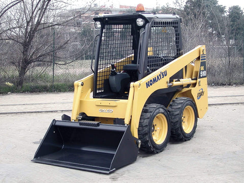
Komatsu SK510-5 Skid Steer Loader Official OEM Workshop Service Repair Manual

Komatsu SK510-5 Skid Steer Loader Workshop Service Repair Manual - Official !!
Exclusive Version & Quality !!
The Best PDF Manuals Online Includes : Bookmarks + Searchable Text + Index = Fast Navigation And Best Organization !
This is the COMPLETE Official Service Repair Manual for the Komatsu SK510-5 Skid Steer Loader.
This manual contains deep information about maintaining, assembly, disassembly and servicing your Komatsu .
This Manual contains information and data to this model.
has specs, diagrams, and actual real photo illustrations, and schemes, which give you complete step by step operations on repair,
servicing, technical maintenance & troubleshooting procedures for your machine.
this manual offers full information you need for repair your machine.
the information in this manual will enable you to find trouble and to understand how to repair and maintain your machine without going into service.
all pages are printable, so run off what you need and take it with you into the garage or workshop.
Model & Serial Number Coverd:
SERIAL NUMBERS SK510-5 - 37DF00001 and up
SERIAL NUMBERS SK510-5 - 37DF00001 and up
Table of Contents:
=========
=========
S10. STRUCTURE AND FUNCTION....................................................................................... 10-1
P.T.O. ........................................................................ 2
Power train ................................................................ 3
Transmission ............................................................. 4
Final drive .................................................................. 6
Hydraulic circuit (standard)........................................ 7
Hydraulic circuit (road homologation) ........................ 8
Hydraulic pump.......................................................... 9
Control valve............................................................ 10
Solenoid valve group ............................................... 11
Accumulator............................................................. 12
R.H. PPC valve........................................................ 13
L.H. PPC valve ........................................................ 14
Cylinders.................................................................. 15
Electrical diagram (engine line) ............................... 17
Electrical diagram (frame line standard) .................. 21
Electrical diagram (cabin line) ................................. 25
Electrical diagram (top-cabin light line standard)..... 31
Electrical diagram
(top-cabin light line homologation)........................... 33
Electrical diagram (standard)................................... 35
20. TESTING AND ADJUSTING ........................................................................................... 20-1
Normal or standard technical data............................. 2
Special tools .............................................................. 8
Checking the engine speed ....................................... 9
Adjustment of valve clearance................................. 10
Measurement of the compression pressure ........... 11
Control and adjustment of the fan belt tension ........ 12
Control and adjustment of the injection timing......... 13
Checking engine oil pressure .................................. 15
Adjusting the stroke of the accelerator cables......... 16
Adjusting the position of the servo-control
engagement safety sensor ...................................... 17
Testing and adjustment of gearing chain tension .... 18
Control and regulation of the pressures in the
hydraulic circuits ...................................................... 19
Testing the hydraulic pump ..................................... 20
Checking the travel deviation .................................. 21
Control valve............................................................ 23
Control and regulation of the servo-control
power supply ........................................................... 24
Elimination of residual pressures - pressurisation of
the tank.................................................................... 26
Bleeding air from the hydraulic circuits.................... 27
30. REMOVAL AND INSTALLATION................................................................................... 30-1
HOW TO READ THE MANUAL................................. 3
PRECAUTIONS TO BE TAKEN WHILE WORKING. 4
ENGINE HOOD
Removal and installation ........................................... 5
CAB
Tinting........................................................................ 6
Lowering .................................................................... 7
BATTERY
Removal and installation ........................................... 8
STARTING MOTOR
Removal and installation ........................................... 9
ALTERNATOR
Removal and installation ......................................... 10
MUFFLER
Removal and installation ......................................... 11
AIR INTAKE FILTER
Removal and installation ......................................... 12
VALVE COVER
Removal and installation ......................................... 13
INJECTORS
Removal and installation ......................................... 14
INJECTION PUMP
Removal .................................................................. 15
Installation ............................................................... 18
CYLINDER HEAD
Removal .................................................................. 19
Installation ............................................................... 21
COOLANT LIQUID PUMP
Removal .................................................................. 22
Installation ............................................................... 23
RADIATOR GROUP
Removal .................................................................. 24
Installation ............................................................... 25
FUEL TANK
Removal .................................................................. 26
Installation ............................................................... 27
CAB
Removal .................................................................. 29
Installation ............................................................... 30
ENGINE-PUMP GROUP
Removal .................................................................. 31
Installation .............................................................. 35
COMPLETE HYDRAULIC PUMP
Removal ...................................................................36
Installation ................................................................38
GEAR PUMP
Removal and installation ..........................................39
ENGINE-PUMP COUPLING
Removal and installation ..........................................40
CONTROL VALVE
Removal and installation ..........................................41
PPC VALVES
Removal and installation ..........................................42
HUB WHEEL
Removal ...................................................................43
Installation ................................................................44
HUB WHEEL
Disassembly .............................................................45
Assembly..................................................................46
FINAL DRIVE
Removal ...................................................................47
Installation ................................................................48
LIFT CYLINDER
Removal and installation ..........................................49
BUCKET CYLINDER
Removal ...................................................................50
Installation ................................................................51
WORK EQUIPMENT CYLINDERS
Disassembly .............................................................52
Assembly..................................................................54
COMPLETE WORKING EQUIPMENT
Removal ...................................................................58
Installation ................................................................59
WORKING EQUIPMENT SUPPORT FRAME
Removal and installation ..........................................60
40. MAINTENANCE STANDARD.......................................................................................... 40-1
P.T.O. ........................................................................ 2
Transmission ............................................................. 3
Final drive .................................................................. 4
Hydraulic pump.......................................................... 5
Control valve.............................................................. 6
Cylinders.................................................................... 7
Working equipment.................................................... 8
-------------------------------
Product Details:
-------------------------------

We Also Recommend

