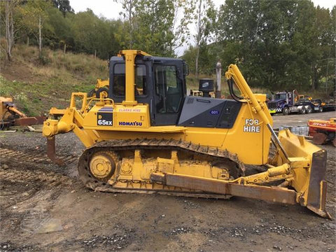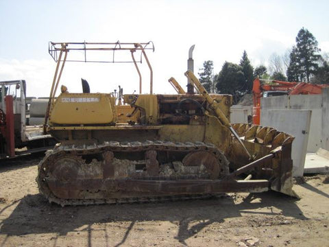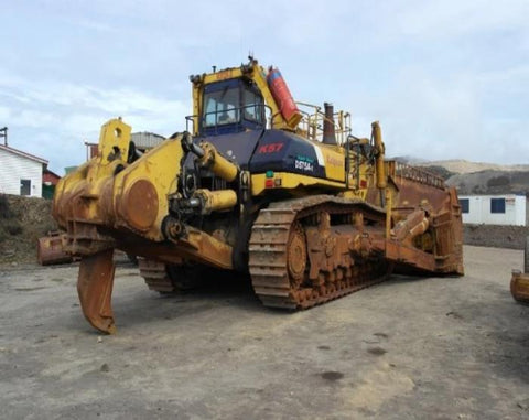
Komatsu D575-2 Super Dozer Official Field Assembly Instruction Manual

Komatsu D575-2 Super Dozer Official Field Assembly Instruction Manual
The Best PDF Manuals Online Includes : Bookmarks + Searchable Text + Index = Fast Navigation And Best Organization !
This is the COMPLETE Official Field Assembly Instruction Manual for the Komatsu Super Dozer.
This manual describes how to assemble the units into the complete
machine in the field.
It's contains information and data to this model. has specs, diagrams, and actual real photo illustrations, and schemes.
This PDF file is Bookmarked and SEARCHABLE to make what you need easy to find.
This Field Assembly Instruction manual provides you with everything you need to know in order to assembly your tractor safely and effectively. Step-by-step assembly procedure, parts installation, adjustment and maintenance procedure after completion of assembly.
Diagrams are provided with the listings to aid the service technician in identifying clearly the parts that need to be ordered.
Models And Serials :
D575A-2E 10012 and up
CONTENTS :
ASSEMBLY PROCEDURE &TIME SCHEDULE
(TRANSPORTED DISASSEMBLED-WEIGHTS LESS THAN 50 TONS) ........3
EQUIPMENT AND TOOLS TO BE USED ........................................................6
TRANSPORTATION POSTURE ...................................................................... 8
INSTALLATION PROCEDURE ........................................................................10
Installation of main unit......................................................................................10
installation of final drive Assembly ...................................................................11
Installation of pivot shaft .................................................................................. 12
Installation of cylinder support ..........................................................................13
Installation of cylinder stay ...............................................................................14
Installation of undercarriage ............................................................................ 14
Installation of track shoe Assembly. ................................................................ 16
Installation of counterweight ............................................................................ 20
Installation of blade lift cylinder ........................................................................ 21
Assembly of super blade Assembly ................................................................. 22
Bleeding air from hydraulic cylinders .............................................................. 27
Standard tightening torque ..............................................................................28
Coating materials ............................................................................................30
Installation of cab ..............................................................................................31
l Electrical circuit diagram. ...............................................................................38
Installation of ROPS ........................................................................................ 41
Installation of external components ................................................................. 42
Exhaust pipes and hoods ................................................................................ 42
Head lamp ....................................................................................................... 43
ROPS light ........................................................................................................44
External cover ................................................................................................. 45
Hand rail ...........................................................................................................46
ASSEMBLY JIG DRAWING ..............................................................................49
APPENDIX
FIELD ASSEMBLY INSPECTION REPORT

We Also Recommend

