Komatsu D475A-5E0 D475ASD-5E0 Bulldozer Official Field Assembly Instruction Manual

Komatsu D475A-5E0 D475ASD-5E0 Bulldozer Official Field Assembly Instruction Manual
The Best PDF Manuals Online Includes : Bookmarks + Searchable Text + Index = Fast Navigation And Best Organization !
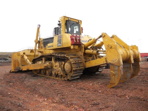
This is the COMPLETE Official Field Assembly Instruction Manual for the Komatsu Bulldozer.
This manual describes how to assemble the units into the complete
machine in the field.
It's contains information and data to this model. has specs, diagrams, and actual real photo illustrations, and schemes.
This PDF file is Bookmarked and SEARCHABLE to make what you need easy to find.
This Field Assembly Instruction manual provides you with everything you need to know in order to assembly your tractor safely and effectively. Step-by-step assembly procedure, parts installation, adjustment and maintenance procedure after completion of assembly.
Diagrams are provided with the listings to aid the service technician in identifying clearly the parts that need to be ordered.
Models And Serials :
D475A- 30001
D475ASD-30001 and up
CONTENTS :
SPECIFICATIONS.................................................................................. 1
PRECAUTIONS FOR FIELD ASSEMBLY.................................................. 3
DISPOSAL OF REMOVED PARTS............................................................ 4
ASSEMBLY PROCEDURE, NECESSARY EQUIPMENT, AND SCHEDULE..... 5
KIT LAYOUT DIAGRAM................................................................................. 6
STYLE FOR TRANSPORTATION.................................................................... 7
TOOLS LIST FOR FIELD ASSEMBLY............................................................ 13
SKETCH OF TOOLS......................................................................................... 16
TIGHTENING TORQUE .............................................................................. 25
COATING MATERIALS.................................................................................. 29
A. ASSEMBLY PROCEDURE........................................................................... 31
A- 1. Setting of track shoe ............................................................................. 32
A- 2. Setting of the machine ........................................................................... 33
A- 3. Installation of blade lift hydraulic cylinder ............................................. 36
A- 4. Installation of undercarriage ................................................................. 42
A- 5. Replacement of return filter
(Replacement of standard filter ➞ special flushing parts).............................. 58
A- 6. Adding oil to pivot chamber ............................................................... 60
A- 7. Check of oil and coolant levels .......................................................... 61
A- 8. Installation of ripper ............................................................................... 63
A- 9. Installation of trunnion.............................................................................. 68
A-10. Installation of track shoe........................................................................ 69
A-11. Check track tension ................................................................................ 72
A-12. Assembly of blade .............................................................................. 74
A-13. Installation of blade.................................................................................. 94
A-14. Installation of operator's cab.................................................................. 102
A-15. Installation of ROPS .............................................................................. 122
A-16. Installing direction of exhaust pipe ........................................................ 123
A-17. Installation of giant ripper shank............................................................. 124
A-18. Adjustment of arm joint (U-blade).......................................................... 125
A-19. Installation of counterweight ................................................................... 126
A-20. Procedure for adjusting blade tilt angle limit............................................ 127
A-21. Method of checking auto-reset system (Superdozer)............................... 136
A-22. Installation of ORBCOMM antenna and wiring harness .......................... 137
A-23. Installing lunchbox band (if equipped) ................................................ 138
A-24. Greasing each part of work equipment.................................................. 140
A-25. Bleeding air from hydraulic cylinders.............................................. 143
A-26. Air bleeding from work equipment pump and fan pump ......................... 144
M. CHECK AND MAINTENANCE PROCEDURES AFTER COMPLETION OF ASSEMBLY......145
M- 1. Check and adjustment of operator’s cab................................................. 146
M- 2. Inspection of machine monitor ................................................................ 153
M- 3. No-injection cranking of engine................................................ 166
M- 4. Setting procedure of user adjust mode ........................... 169
M- 5. Flushing of hydraulic circuit.................................................................... 172
APPENDIX 1
INSTALLATION OF SPILL GUARDS
APPENDIX 2
PRECAUTIONS FOR INITIALIZATION PROCEDURES FOR VHMS CONTROLLER
FIELD ASSEMBLY INSPECTION REPORT (U-DOZER SPECIFICATION)
FIELD ASSEMBLY INSPECTION REPORT (SUPERDOZER SPECIFICATION)

We Also Recommend