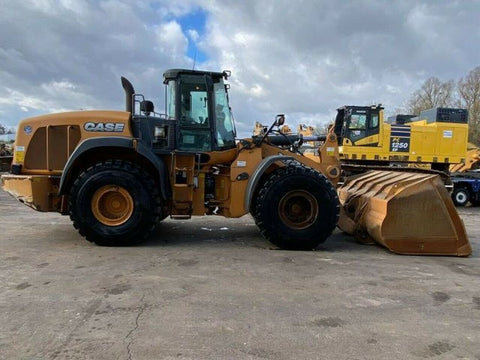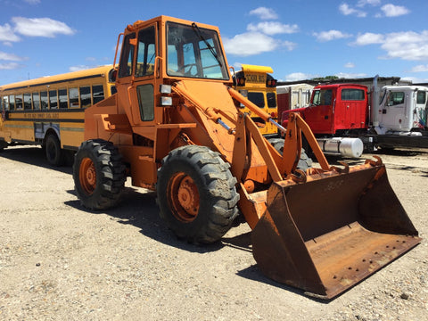
Case W14B Wheel Loaders Official Workshop Service Repair Manual

Case W14B Wheel Loaders Official Workshop Service Repair Manual
The Best PDF Manuals Online Includes : Bookmarks + Searchable Text + Index = Fast Navigation And Best Organization !
This is the COMPLETE Official Service Repair Manual for the Case W14B Wheel Loaders.
This manual contains deep information about maintaining, assembly, disassembly and servicing your Wheel Loader.
This PDF file is Bookmarked and SEARCHABLE to make what you need easy to find.
which give you complete step by step operations on repair, servicing, technical maintenance & troubleshooting procedures for your machine.
this manual offers full information you need for repair your machine.
the information in this manual will enable you to find trouble and to understand how to repair and maintain your machine without going into service.
all pages are printable, so run off what you need and take it with you into the garage or workshop.
Models & Serials Covered:
8-42830-R1
Table of Contents:
1 GENERAL
Safety Rules, Service Manual Introduction, and
Torque Specifications 1001
Fluids and Lubricants Chart, Maintenance Chart 1002
General Engine Specifications 1010
Detailed Engine Specifications 1024
2 ENGINE
Engine Removal and Installation, Radiator Removal
and Installation 2000
Engine Accessories (Air Cleaner, Ether Injection,
Mufflers, Turbocharger) 2001
Stall Tests 2002
Cylinder Head and Valve Train 2415
Cylinder Block, Crankshaft, Pistons, Rods, Camshaft,
Oil Seals, Flywheel, and Crankshaft 2425
Lubrication System 2445
Cooling System 2455
Turbocharger (Teardown) 2465
Turbocharger Failure Analysis 2565
3 FUEL SYSTEM
Fuel lines , Fuel Tank, and Engine Controls 3001
Fuel System and Filters 3410
Bosch Fuel Injection Pump, Drive Gear Timing 3412
Fuel Injectors 3413
4 ELECTRICAL SYSTEM
Removal and Installation of Electrical Components 4001
Specifications and Troubleshooting 4002
Wiring Diagrams Rear Pocket
Instrument Cluster and Optional Gauges 4004
Batteries 4005
Starter and Starter Solenoid 4006
40 Ampere Alternator 4017
65 Ampere Alternator 4018
5 STEERING
Removal and Installation of Steering
Components 5000
Troubleshooting and Pressure Check 5002
Hydraulic Schematic Rear Pocket
Steering Control Valve 5007
Flow Control Valve 5008
Center Pivot 5023
Auxiliary Steering Pump and Check Valve 5025
Steering Cylinder See Section 8090
6 POWER TRAIN
Removal and Installation of Transmission, Axles,
and Differentials 6100
Maintenance 6101
Troubleshooting and Pressure Checks 6102
Torque Converter, Transmission, and Control Valve 6 1 1 O
Transmission Controls 6 1 1 1
Drive Shafts and Trunnions 6125
Differential and Planetary 6126
Wheels and Tires 6129
7 BRAKES
Removal and Installation of Brake System Components 7100
Specifications, Diagram, Troubleshooting, Leakage Tests,
and Adjustments 7102
Air Compressor and Governor 7103
Reservoirs and Relief Valve 7104
Brake Valve 7105
Brake Actuator 7107
Pressure Reducing Valve and Pressure Protection Valve 7109
Air Horn and Air Valve 7110
Disc Brake 7121
Parking Brake Actuator and Parking Brake Valve 7126
8 HYDRAULIC
Removal and Installation of Hydraulic System Components 8000
Maintenance 8001
Specifications, Troubleshooting and Pressure Checks 8002
Hydraulic Diagram Rear Pocket
Cleaning the Hydraulic System 8003
Pump 8005
Loader Control Valve 8007
Cylinders 8090
9 MOUNTED EQUIPMENT
Air Conditioning Troubleshooting 9002
Air Conditioning System 9003
Loader 9010
ROPS Cab and Canopy 9061
Seat and Seat Belts 9064
Noise Control 9201
REAR POCKET
Electrical Schematic - Front Harness
Electrical Schematic - Rear Harness
Electrical Schematic - Cab
HydrauIic Schematic
========================================
Product Details :

We Also Recommend

