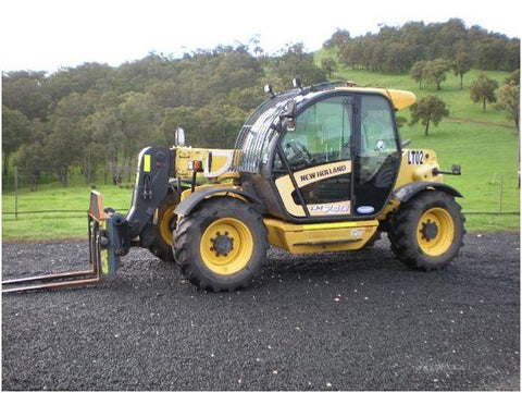
New Holland LM740 Telehandlers Official Workshop Service Repair Technical Manual

New Holland LM740 Telehandlers Official Workshop Service Repair Technical Manual
The Best PDF Manuals Online Includes : Bookmarks + Searchable Text + Index = Fast Navigation And Best Organization !
This is the COMPLETE Official Service Repair Manual for the New Holland Telehandlers .
This manual contains deep information about maintaining, assembly, disassembly and servicing your New Holland .
This PDF file is Bookmarked and SEARCHABLE to make what you need easy to find.
This Manual contains information and data to this model. has specs, diagrams, and actual real photo illustrations, and schemes, which give you complete step by step operations on repair, servicing, technical maintenance & troubleshooting procedures for your machine. this manual offers full information you need for repair your machine. the information in this manual will enable you to find trouble and to understand how to repair and maintain your machine without going into service. all pages are printable, so run off what you need and take it with you into the garage or workshop.
Models And Serials :
All Years & Serials Covered
-
SECTION 00 - GENERAL
- General instructions
- Safety rules
- Product identification
- Environmental considerations
- Maintenance techniques
-
SECTION 10 – ENGINE
- Main engine specifications
- General engine specifications
- General information on F4GE9484J*J600 engine
- Removal and installation of engine and radiator
- Troubleshooting
- Tightening torques
-
SECTION 21 - POWERSHIFT TRANSMISSION
- Transmission assembly
- Drop box assembly
- Operation of gearbox
- Transmission and hydraulic oil circuit diagrams
- Operation of modulating valve
- Torque converter and oil cooler hydraulic circuit
- Troubleshooting guide
- Troubleshooting procedures
- Troubleshooting
- Pressure tests on clutch and high pressure circuit
- Pressure tests on torque converter and oil cooler hydraulic circuit
- Test points
- Assembly instructions
- Transmission overhaul
- Special tools
-
SECTION 25 - FRONT AXLE
- Technical data
- Description
- Operation
- Troubleshooting
- Wheel toe--in check
- Component overhaul
- Front axle removal procedure
- Front axle overhaul
- Adjusting the axle drive pinion bearing
- Installation and adjustment of axle drive pinion
- Front drive shaft
-
SECTION 27 - REAR AXLE
- Technical data
- Description
- Operation diagram
- Component overhaul
- Rear axle removal procedure
- Overhaul
- Special tools
-
SECTION 33 - BRAKING SYSTEM
- Service brakes
- Trailer brake
- Parking brake
- Brake disc adjustment
- Troubleshooting
- Brakes disassembly
-
SECTION 35 – HYDRAULIC SYSTEM
- Technical data
- Steering system hydraulic circuit
- Description and operation
- Introduction
- Steering valve
- Telescopic boom hydraulic circuit
- Hydraulic pump
- Pressure reducing valve
- Front loader controls/ operation
- Balancing valves
- Power steering (OSPQ)
- Telescopic boom distributor
- Auxiliary control distributor (without stabilisers)
- Cylinders
- Boom
-
SECTION 55 – ELECTRICAL SYSTEM
- Chapter 1 – Electrical system - General
- Electrical equipment specifications
- Electrical system and fuses
- Controls and instruments
- Procedure for calibrating the tip--over prevention system
- Bulb replacement
- Protecting the electrical systems during charging or welding
- Starting the machine using jump leads
- Temporary wiring repairs
- Electrical system – general fault finding
- Chapter 2 – Circuit diagrams
- List of connectors
- List of components
- How to use the circuit diagrams
- Diagram 1: Starting/recharge/warning lights/indicators
- Diagram 2: Transmission
- Diagram 3: Wheel alignment/solenoid valves/brake system
- Diagram 4: Boom control
- Diagram 5: Lights/windscreen wiper
- Diagram 6: Work lights/beacon
- Diagram 7: Tip--over prevention system/roof wiper
- Diagram 8: Heater, radio/trailer socket/interior light
- Diagram 9: Air--conditioning system
- Diagram 10: Rear attachment (optional)
-
SECTION 60 – AIR CONDITIONING SYSTEM
- Air conditioning system
- Operation
- Cab heating-ventilation controls
- Precautions for use
- Connections for servicing tools
- Draining the refrigerant
- Recharging with refrigerant
- Leak test
- Special tools
- Fault finding

We Also Recommend